
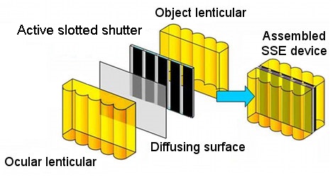
An SSE device includes three main parts which are available on the market:
- A dual lenticular lens, which comprises of a pair of lenticular lenses (one layer oriented towards a screen, and another towards a viewer) of the same pitch.
- An active modulator/commutator of light stream which is a cyclically moving vertical slit layer
- Scattering (luminal) surface.
The elements of an SSE unit and the entire optical construction are as follows:
A lenticular lens is a layer made of optical material (glass or plastic), the one side of which is flat and the other is formed of small cylindrical lenses. The surface of such lenticular lens is formed from adjacent uniform cylindrical lenses which are arranged in parallel (in true or flattened Fresnel versions). Their optical construction is quite close to the axial rays, corresponding to elementary/geometrical optics according to the small size of lenses of a commercially available lenticular (i.e. small curvature and height of the cylindrical segments). Lenticulars are available in variety of sizes, as they are produced industrially by many manufacturers and do not constitute any shortage in supply. The lenticular lenses mostly are used in printing industry (for production of lenticular cards and other printing products), in advertising, and in interior design, as well as in special applications for planar optics.
The ocular part of SSE, i.e. a lenticular lens and scattering surface, is similar to the widely used “stripping” technology – a printing technology of graphic synthesis and rendering of multi-perspective images (example: lenticular cards). This “printing” technology can be easily explained by the following illustration for R = 4 perspectives and a lenticular lens with L = 5 lenses through view width (perspectives are assumed to have the same horizontal-parallax):
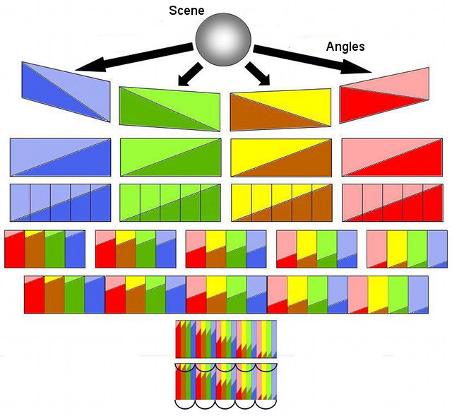
The whole process (from top to bottom of the figure) that is valid for all R and L comprises the following steps:
- A scene is shot from R perspectives, which are uniform – have similar parallax and same scale.
- Horizontal inversion (turning from left to right) of each perspective is performed.
- Each view is divided into L vertical stripes of equal width.
- Non-repetetive ordered strip sets are assembled for each micro-lens.
- The strip sets for all lenses are ordered and combined into a single image.
- The combined image is compressed horizontally R times (the result of the compression is called a Lippmann-Bonnet chart).
- A lenticular lens is imposed onto the Lippmann-Bonnet chart.